Laser Distance Sensor in Pre-bending Control for Rails Entering the Cooling Bed in the Hot Rolling Process
The Need for Pre-bending Control in the Hot Rolling Process
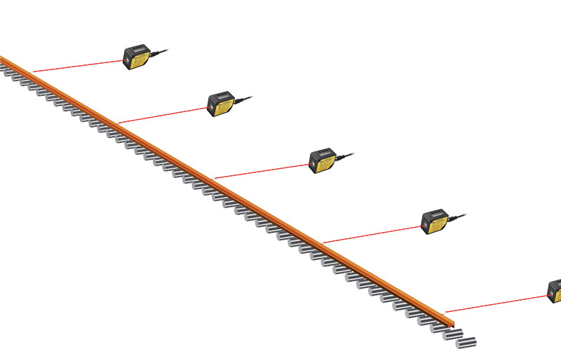
In hot rolling, rails are shaped at high temperatures and gradually cooled down. During cooling, the metal is prone to deformation, which is especially pronounced over long cooling periods, affecting the rail's final straightness. Pre-bending control before the rails enter the cooling bed helps to minimize unwanted deformations during cooling, ensuring a straight and uniform final product.
Working Principle of the Laser Distance Sensor
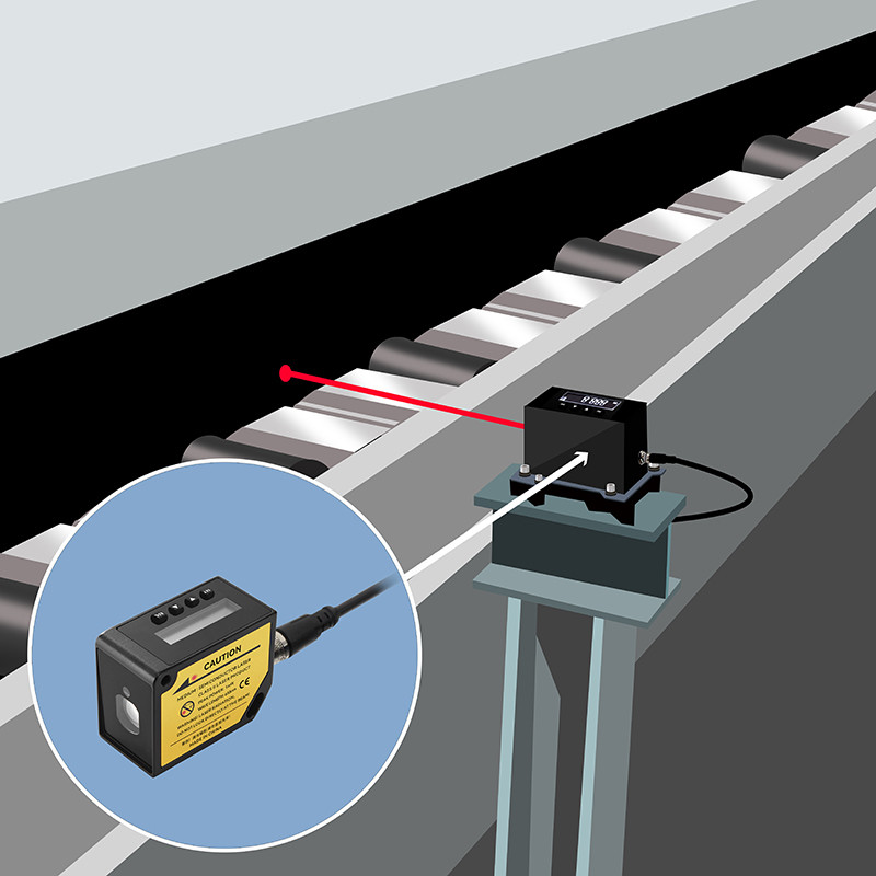
A laser distance sensor operates on the principle of non-contact distance measurement, often using techniques like triangulation or Time of Flight (TOF). In pre-bending control, the sensor emits a laser beam and, through optical components, detects the reflected signal. By measuring either the time delay or angle variation of the laser reflection, it precisely calculates the measuring distance between the rail and the sensor. This non-contact measurement method offers fast response and high accuracy, ideal for real-time feedback in the pre-bending stage.
Application of Laser Distance Sensor in Pre-bending Control
In hot rolling production, the laser distance sensor is mainly used for pre-bending control before the rails enter the cooling bed. Its applications include:
Application of Laser Distance Sensor in Pre-bending Control
Real-time Monitoring of Rail Position and Curvature: Installed near the pre-bending equipment, the laser distance sensor continuously measures the distance from the sensor to the rail surface, providing real-time feedback on the rail's position and bending degree.
Feedback Adjustment to Pre-bending System: With accurate distance measurement data provided by the laser distance sensor, the pre-bending system can quickly adjust the rail's angle and bending parameters, ensuring that the rail is in the ideal pre-bending position before entering the cooling bed.
Enhanced Production Precision and Consistency: The laser distance sensor’s high-frequency, precise data collection minimizes issues related to cooling deformation, improving product consistency and reducing the need for later adjustments.
Advantages of Laser Distance Sensor in Pre-bending Control
Non-contact Measurement, Reducing Equipment Wear: Unlike traditional contact measurement methods, the laser distance sensor can perform distance measurement in high-temperature environments without physical contact, avoiding equipment wear and temperature-related effects, thus extending the equipment’s service life.
High-precision Measurement for Rail Straightness After Cooling: The laser distance sensor’s high precision ensures that the rail remains in the optimal bending state before cooling, minimizing post-cooling deformation and resulting in straighter finished rails.
Fast Response, Improving Production Efficiency: The laser distance sensor’s rapid response allows for real-time rail position and condition feedback, helping production equipment make timely adjustments, increasing efficiency, and reducing manual adjustment errors.
Your Possible Solutions
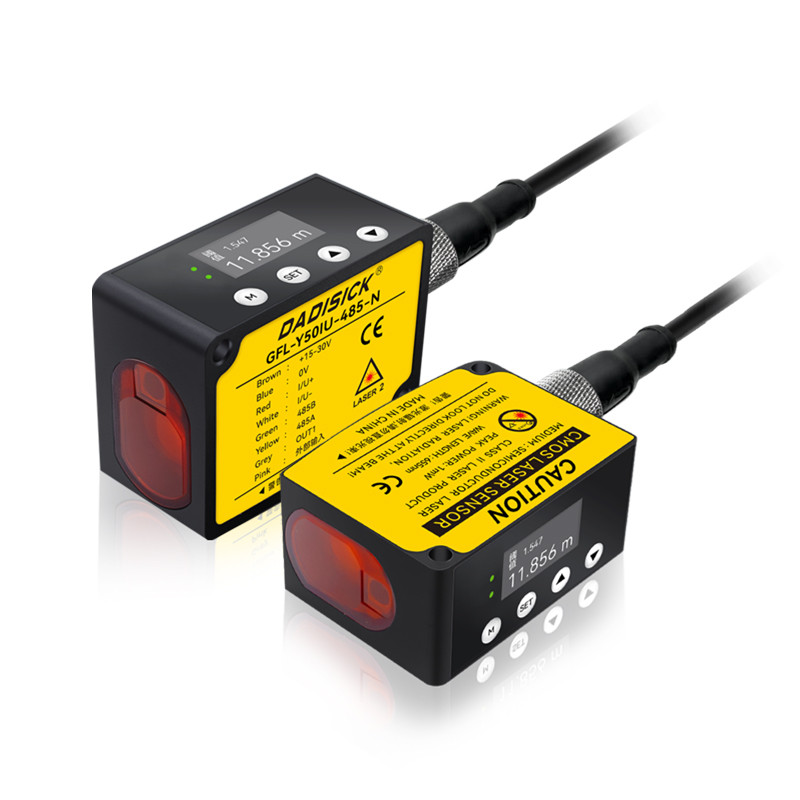
GFL-Y Series: Compact High-Precision Laser Distance Sensor for Various Industrial Measurement Needs
The GFL-Y Series uses phase-shift distance measurement, enabling fast and precise measurement with a range covering 1m, 2m, 5m, 10m, 20m, and 50m. It can be configured without a computer and includes baud rate and station number selection, supporting networking of up to 255 devices. Compatible with PLC systems or Boyi Jingke software, it is highly adaptable to various industrial settings. With a metal housing and an IP67 rating, the sensor offers excellent dust and water resistance, ensuring durability in demanding environments.
|
Output type
|
NPN+Analog+RS485
|
PNP+Analog+RS485
|
Measurement range
|
|
Models
|
GFL-Y01IU-485-N
|
GFL-Y01IU-485-P
|
0.1 - 1 m
|
|
GFL-Y02IU-485-N
|
GFL-Y02IU-485-P
|
0.1 - 2 m
|
|
|
GFL-Y05IU-485-N
|
GFL-Y05IU-485-P
|
0.1 - 5 m
|
|
GFL-Y10IU-485-N | GFL-Y10IU-485-P | 0.1 - 10 m | |
GFL-Y20IU-485-N | GFL-Y20IU-485-P | 0.1 - 20 m | |
GFL-Y50IU-485-N | GFL-Y50IU-485-P | 0.1 - 50 m | |
Resolution | 1 mm | ||
Measurement Error | ±(2 mm + d * 0.01%)★ | ||
Laser Type | Red semiconductor laser, Class II, 655 ± 10 nm, <1 mW | ||
Current Consumption | ≤50 mA at 24V | ||
Power Supply Voltage | 12–24V DC, with ±10% fluctuation (P-P) <10% | ||
Control Output | NPN or PNP open-collector output, with a maximum current of 50 mA, external voltage <30V DC, residual voltage <1.5V, and leakage current <0.1 mA | ||
Output Mode | Switchable between NO (normally open) and NC (normally closed) | ||
Short-Circuit Protection | Auto-reset type | ||
Analog Voltage Output | Range 0–5V (5.2V in alarm mode), output impedance 100Ω | ||
Analog Current Output | Range 4–20 mA (0 mA in alarm mode), load impedance <3000Ω | ||
Response Time | 50–200 ms | ||
External Input | NPN non-contact input | ||
Protection Rating | IP67 | ||
Operating Temperature | -10°C to +45°C (avoid condensation and icing) | ||
Storage Temperature | -20°C to +60°C | ||
Operating Humidity | Incandescent light, up to 3000 LX | ||
Operating Altitude | Up to 2000 m | ||
Cable | 8-core composite cable, 2 m length | ||
Material | Aluminum alloy | ||
★ Note | Measurement distance may vary in challenging environments, such as intense sunlight, high humidity fluctuations, or low-reflectivity surfaces. Using a target reflector plate is recommended to improve accuracy under these conditions. | ||
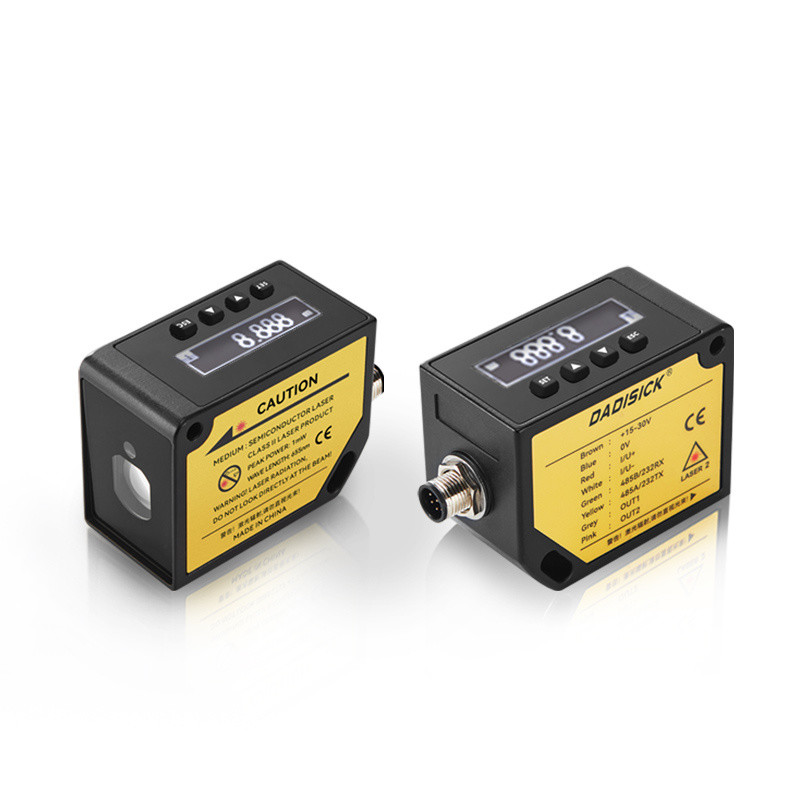
DA-Y & DB-Y Series: Multi-Functional Laser Distance Sensors with Long-Range Measurement and Easy Configuration
The DA-Y and DB-Y Series also utilize phase-shift measurement, delivering high precision and fast measurement across ranges of 10m, 20m, 30m, 50m, and up to 100m. Equipped with a built-in display and menu, they can be configured directly without a computer. Supported outputs include RS232 / RS485, dual switch outputs, and voltage/current outputs, making them suitable for PLC programming and networking of up to 64 devices. The die-cast metal housing with an IP67 rating ensures reliable performance in outdoor and harsh environments.
|
Output type
|
Digital+Switch output
|
Digital+Switch+Analog
|
Measurement range
|
|
Models
|
DA-Y10
|
DB-Y10
|
0.2 - 10 m
|
|
DA-Y20
|
DB-Y20
|
0.2 - 20 m
|
|
|
DA-Y30
|
DB-Y30
|
0.2 - 30 m
|
|
DA-Y50 | DB-Y50 | 0.2 - 50 m | |
DA-Y100 | DB-Y100 | 0.2 - 100 m | |
Measurement Frequency | 1 - 40 Hz | ||
Voltage/Current Output Options | Configurable as 0–5V, 0–10V, 4–20 mA, 0–20 mA, or 0–24 mA★2 | ||
Voltage Output Error | — | 0.2% + 0.5 mV | — |
Current Output Error | — | 0.2% + 0.005 mA | — |
Communication Interface | — | Switchable between RS232 and RS485 | — |
Laser Type | Class II, 660 ± 15 nm, ≤1 mW | ||
Resolution | 1 mm | ||
Measurement Error | ±(2 mm + d * 0.01%)★1 | ||
Indicator Beam | Red laser | ||
Spot Size | ⌀6 mm at 1 m, ⌀8 mm at 10 m, ⌀12 mm at 20 m, ⌀16 mm at 30 m | ||
Display | 128x32 dot-matrix display | ||
Backlight Off Time | 30 minutes (can be set to stay on continuously) | ||
Operating Modes | Measurement off, continuous measurement | ||
Transistor Switching Output | 2 outputs (not to exceed DC 36V, 0.5A)★3 | ||
Power Supply | DC 15 - 30V | ||
Power Consumption | <3.0 W | ||
Protection Rating | IP67 | ||
Body Material | Die-cast zinc alloy | ||
Operating Temperature | -10°C to +50°C | ||
Storage Humidity | -20°C to +60°C, 20% ~ 85% RH | ||
Overheat Protection | Measurement stops when body temperature exceeds 70°C, resumes below 70°C | ||
Dimensions | 88.45 x 40 x 59.3 mm (including connection base) | ||
★ Note 1 | Measurement accuracy may vary depending on actual distance ("d") and environmental factors. In challenging environments, such as strong sunlight or significant temperature fluctuations, using a target reflector plate is recommended to improve accuracy. | ||
★ Note 2 | 88.45 x 40 x 59.3 mm (including connection base) | ||
★ Note 3 | Exceeding the specified voltage or current for transistor switching output may result in permanent damage to the device. | ||